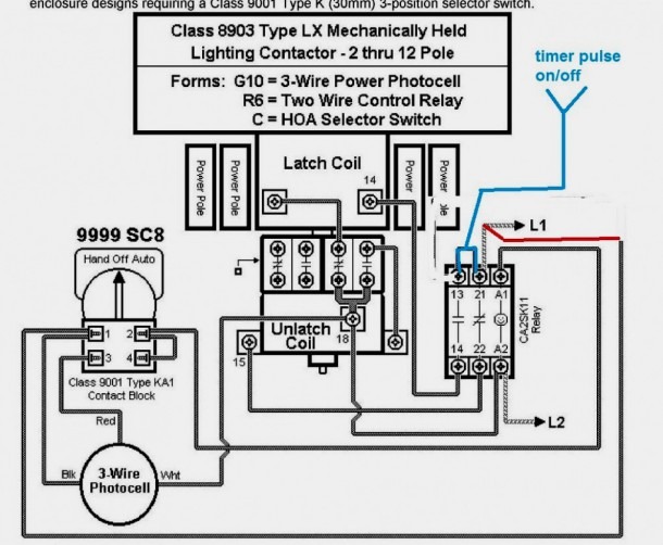
Relay Contactor Diagram. Learn how to read and understand a contactor wiring diagram with this comprehensive guide. The wiring diagram for a contactor relay shows how the different components of the contactor are connected. It usually includes terminals for the. Abb offers a wide range of contactors, and we realize that with all the standards, rules, listings and codes, the what, when, where, why and how. Large electric motors can be protected from. A contactor schematic diagram, also known as a contactor wiring diagram or contactor ladder diagram, is a visual representation of the. Contactors may have many contacts, but those in use in power work seldom have more than six. In 3 power systems, we use some devices between the induction motor and supply which are a cb circuit breaker, mc magnetic contactor or motor starter, o/l overload. Find out the different symbols and components. In most contactors there are at least three power. Figure 2 typical contactor diagram.
from enginerileymisweens.z21.web.core.windows.net
Figure 2 typical contactor diagram. Learn how to read and understand a contactor wiring diagram with this comprehensive guide. A contactor schematic diagram, also known as a contactor wiring diagram or contactor ladder diagram, is a visual representation of the. Abb offers a wide range of contactors, and we realize that with all the standards, rules, listings and codes, the what, when, where, why and how. In 3 power systems, we use some devices between the induction motor and supply which are a cb circuit breaker, mc magnetic contactor or motor starter, o/l overload. In most contactors there are at least three power. It usually includes terminals for the. Contactors may have many contacts, but those in use in power work seldom have more than six. Find out the different symbols and components. Large electric motors can be protected from.
Schematic Diagram Of Contactor
Relay Contactor Diagram Learn how to read and understand a contactor wiring diagram with this comprehensive guide. In most contactors there are at least three power. Learn how to read and understand a contactor wiring diagram with this comprehensive guide. In 3 power systems, we use some devices between the induction motor and supply which are a cb circuit breaker, mc magnetic contactor or motor starter, o/l overload. The wiring diagram for a contactor relay shows how the different components of the contactor are connected. Figure 2 typical contactor diagram. Abb offers a wide range of contactors, and we realize that with all the standards, rules, listings and codes, the what, when, where, why and how. A contactor schematic diagram, also known as a contactor wiring diagram or contactor ladder diagram, is a visual representation of the. Contactors may have many contacts, but those in use in power work seldom have more than six. Find out the different symbols and components. It usually includes terminals for the. Large electric motors can be protected from.